> ## Documentation Index
> Fetch the complete documentation index at: https://docs.t3gemstone.org/llms.txt
> Use this file to discover all available pages before exploring further.
# PWM
> Pulse Width Modulation (PWM)
export const int_0 = "Interface"
export const device_0 = "Device"
export const file_0 = "Overlay File"
PWM (Pulse Width Modulation) is a modulation technique used to control the average power level of a signal.
Its basic working principle relies on adjusting the "on" and "off" durations (duty cycle) of a square wave
with a fixed period. In embedded systems, it is used for various purposes such as motor speed control, LED
brightness adjustment, servo motor control, power converters, and analog signal generation. For example,
when controlling a motor's speed with PWM, as the duty cycle value increases, the average voltage delivered
to the motor increases, causing the motor to rotate faster.
The **period**, one of the fundamental parameters of a PWM signal, is the duration of one complete waveform
cycle. The **duty cycle** is the duration during which the signal remains "on" within one period.
**Polarity** determines the active state of the PWM signal (high or low level). For instance, in normal
polarity, the duty cycle represents the high level, while in inverted polarity, it represents the low level.
### PWM Interfaces
The PWM interfaces available on the T3-GEM-O1 board are listed in the table below.
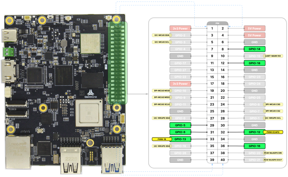 | {int_0} | {device_0} | GPIO | {file_0} |
| ------------- | --------------- | ---------- | ------------------------------------------ |
| **PWM-ECAP0** | `pwmchip0/pwm0` | GPIO-12 | `k3-am67a-t3-gem-o1-pwm-ecap0-gpio12.dtso` |
| **PWM-ECAP1** | `pwmchip1/pwm0` | GPIO-16 | `k3-am67a-t3-gem-o1-pwm-ecap1-gpio16.dtso` |
| **PWM-ECAP2** | `pwmchip2/pwm0` | GPIO-18 | `k3-am67a-t3-gem-o1-pwm-ecap2-gpio18.dtso` |
| **PWM-0A** | `pwmchip3/pwm0` | GPIO-5 | `k3-am67a-t3-gem-o1-pwm-epwm0-gpio5.dtso` |
| **PWM-0B** | `pwmchip3/pwm1` | GPIO-14 | `k3-am67a-t3-gem-o1-pwm-epwm0-gpio14.dtso` |
| **PWM-1A** | `pwmchip5/pwm0` | GPIO-6 | `k3-am67a-t3-gem-o1-pwm-epwm1-gpio6.dtso` |
| **PWM-1B** | `pwmchip5/pwm1` | GPIO-13 | `k3-am67a-t3-gem-o1-pwm-epwm1-gpio13.dtso` |
| **PWM-2A** | `pwmchip7/pwm0` | FAN header | `k3-am67a-t3-gem-o1-gpio-fan.dtso` |
To enable PWM-0A and PWM-0B together: `k3-am67a-t3-gem-o1-pwm-epwm0-gpio5-gpio14.dtso`
To enable PWM-1A and PWM-1B together: `k3-am67a-t3-gem-o1-pwm-epwm1-gpio6-gpio13.dtso`
The `pwmchip3` and `pwmchip5` chips have two channels, and each channel can be used as a PWM device.
However, **different period values CANNOT be assigned** to the two channels of a single PWM chip
(e.g., PWM-0A and PWM-0B). As long as the same period value is given to both channels, there is no
issue in assigning different duty cycles.
The names of the overlay files for the interfaces to be enabled must be added to the `overlays` variable
in the `/boot/uEnv.txt` file. Detailed information about overlays can be found in the
[Device Tree](./introduction/#2-device-tree) section.
When all overlays are enabled, there are **8 separate PWM interfaces** available: 1 from the FAN header
and 7 from the 40-pin header.
### PWM Usage
PWM chips can be accessed via the `/sys/class/pwm` directory. Before using a PWM device, an `export` operation
must be performed. For example, referring to the table above, the `PWM-ECAP0` interface corresponds to the
`pwm0` device of the `pwmchip0` chip. After executing the following command, the `/sys/class/pwm/pwmchip0/pwm0`
device will be created. The reason for writing `echo 0` is that it corresponds to `pwm0`, i.e., device number `0`.
```bash theme={"system"}
gemstone@t3-gem-o1:~$ echo 0 | sudo tee /sys/class/pwm/pwmchip0/export
# 0
```
Similarly, if the `PWM-0B` interface is to be used, the `pwm1` device of the `pwmchip3` chip should be activated
as shown in the following command. The reason for writing `echo 1` is that it corresponds to `pwm1`, i.e.,
device number `1`.
```bash theme={"system"}
gemstone@t3-gem-o1:~$ echo 1 | sudo tee /sys/class/pwm/pwmchip3/export
# 1
```
After the `export` operation, the `period` and `duty_cycle` variables (in nanoseconds) can be set to desired
values as shown in the example below. Once the `enable` variable is set to `1`, the PWM output can be obtained.
```bash theme={"system"}
gemstone@t3-gem-o1:~$ echo 2000000 | sudo tee /sys/class/pwm/pwmchip0/pwm0/period # 500 Hz
# 2000000
gemstone@t3-gem-o1:~$ echo 1000000 | sudo tee /sys/class/pwm/pwmchip0/pwm0/duty_cycle # 50%
# 1000000
gemstone@t3-gem-o1:~$ echo 1 | sudo tee /sys/class/pwm/pwmchip0/pwm0/enable
# 1
```
To stop the PWM output, set the `enable` variable to `0`.
```bash theme={"system"}
gemstone@t3-gem-o1:~$ echo 0 | sudo tee /sys/class/pwm/pwmchip0/pwm0/enable
# 1
```
If the PWM device is no longer needed, an `unexport` operation can be performed. This will remove the
device from the system. The reason for writing `echo 0` is that it corresponds to `pwm0`, i.e., device number `0`.
```bash theme={"system"}
gemstone@t3-gem-o1:~$ echo 0 | sudo tee /sys/class/pwm/pwmchip0/unexport
# 0
```
| {int_0} | {device_0} | GPIO | {file_0} |
| ------------- | --------------- | ---------- | ------------------------------------------ |
| **PWM-ECAP0** | `pwmchip0/pwm0` | GPIO-12 | `k3-am67a-t3-gem-o1-pwm-ecap0-gpio12.dtso` |
| **PWM-ECAP1** | `pwmchip1/pwm0` | GPIO-16 | `k3-am67a-t3-gem-o1-pwm-ecap1-gpio16.dtso` |
| **PWM-ECAP2** | `pwmchip2/pwm0` | GPIO-18 | `k3-am67a-t3-gem-o1-pwm-ecap2-gpio18.dtso` |
| **PWM-0A** | `pwmchip3/pwm0` | GPIO-5 | `k3-am67a-t3-gem-o1-pwm-epwm0-gpio5.dtso` |
| **PWM-0B** | `pwmchip3/pwm1` | GPIO-14 | `k3-am67a-t3-gem-o1-pwm-epwm0-gpio14.dtso` |
| **PWM-1A** | `pwmchip5/pwm0` | GPIO-6 | `k3-am67a-t3-gem-o1-pwm-epwm1-gpio6.dtso` |
| **PWM-1B** | `pwmchip5/pwm1` | GPIO-13 | `k3-am67a-t3-gem-o1-pwm-epwm1-gpio13.dtso` |
| **PWM-2A** | `pwmchip7/pwm0` | FAN header | `k3-am67a-t3-gem-o1-gpio-fan.dtso` |
To enable PWM-0A and PWM-0B together: `k3-am67a-t3-gem-o1-pwm-epwm0-gpio5-gpio14.dtso`
To enable PWM-1A and PWM-1B together: `k3-am67a-t3-gem-o1-pwm-epwm1-gpio6-gpio13.dtso`
The `pwmchip3` and `pwmchip5` chips have two channels, and each channel can be used as a PWM device.
However, **different period values CANNOT be assigned** to the two channels of a single PWM chip
(e.g., PWM-0A and PWM-0B). As long as the same period value is given to both channels, there is no
issue in assigning different duty cycles.
The names of the overlay files for the interfaces to be enabled must be added to the `overlays` variable
in the `/boot/uEnv.txt` file. Detailed information about overlays can be found in the
[Device Tree](./introduction/#2-device-tree) section.
When all overlays are enabled, there are **8 separate PWM interfaces** available: 1 from the FAN header
and 7 from the 40-pin header.
### PWM Usage
PWM chips can be accessed via the `/sys/class/pwm` directory. Before using a PWM device, an `export` operation
must be performed. For example, referring to the table above, the `PWM-ECAP0` interface corresponds to the
`pwm0` device of the `pwmchip0` chip. After executing the following command, the `/sys/class/pwm/pwmchip0/pwm0`
device will be created. The reason for writing `echo 0` is that it corresponds to `pwm0`, i.e., device number `0`.
```bash theme={"system"}
gemstone@t3-gem-o1:~$ echo 0 | sudo tee /sys/class/pwm/pwmchip0/export
# 0
```
Similarly, if the `PWM-0B` interface is to be used, the `pwm1` device of the `pwmchip3` chip should be activated
as shown in the following command. The reason for writing `echo 1` is that it corresponds to `pwm1`, i.e.,
device number `1`.
```bash theme={"system"}
gemstone@t3-gem-o1:~$ echo 1 | sudo tee /sys/class/pwm/pwmchip3/export
# 1
```
After the `export` operation, the `period` and `duty_cycle` variables (in nanoseconds) can be set to desired
values as shown in the example below. Once the `enable` variable is set to `1`, the PWM output can be obtained.
```bash theme={"system"}
gemstone@t3-gem-o1:~$ echo 2000000 | sudo tee /sys/class/pwm/pwmchip0/pwm0/period # 500 Hz
# 2000000
gemstone@t3-gem-o1:~$ echo 1000000 | sudo tee /sys/class/pwm/pwmchip0/pwm0/duty_cycle # 50%
# 1000000
gemstone@t3-gem-o1:~$ echo 1 | sudo tee /sys/class/pwm/pwmchip0/pwm0/enable
# 1
```
To stop the PWM output, set the `enable` variable to `0`.
```bash theme={"system"}
gemstone@t3-gem-o1:~$ echo 0 | sudo tee /sys/class/pwm/pwmchip0/pwm0/enable
# 1
```
If the PWM device is no longer needed, an `unexport` operation can be performed. This will remove the
device from the system. The reason for writing `echo 0` is that it corresponds to `pwm0`, i.e., device number `0`.
```bash theme={"system"}
gemstone@t3-gem-o1:~$ echo 0 | sudo tee /sys/class/pwm/pwmchip0/unexport
# 0
```