1. Overview
ArduPilot is a mature, feature-rich open-source autopilot system supporting various vehicle types including planes, copters, rovers, and submarines. This guide covers running ArduPilot on T3 Gemstone O1 development boards.2. Hardware Specifications
Inertial Measurement Unit (IMU)
- Model: InvenSense ICM-20948
- Interface: SPI
Magnetometer (Compass)
- Model: AKM AK09916
- Interface: Internal (via ICM-20948)
- External I2C Compass Probing: Enabled
Barometer
- Model: Bosch BMP390
- Interface: SPI
CAN Bus
- Transceiver: TCAN1462-Q1
- Interface: 1x CAN interface available
Battery Monitor
- Model: ADS1115
- Interface: Can be connected externally via I2C-MCU0 at address 0x48
- Channels: 4-channel 16-bit ADC for voltage/current sensing
Status Indicators
- LEDs: Green-red status LEDs
- Buzzer: Can be connected externally via GPIO-26
GPS, RC Input & PWM Outputs
- GPS: Serial communication via UART-MAIN6, external compass via I2C-MCU0
- RC Input: SBUS communication via UART-MAIN1
- PWM Outputs: 7x hardware PWM channels accessible from 40-pin GPIO header
3. Installation
ArduPilot is distributed as a Debian package via the T3 Gemstone APT repository. The package includes pre-compiled binaries for all vehicle types and necessary configuration files.If you prefer to compile ArduPilot from source, build instructions are available at
github.com/t3gemstone/ardupilot
3.1. Device-tree Overlays
Before running ArduPilot, you must enable the required device-tree overlays to configure the necessary peripherals. Edit/boot/uEnv.txt and append the following overlays to the overlays= line:
/boot/uEnv.txt configuration:
3.2. Systemd Service Management
Each ArduPilot vehicle type has its own systemd service:arducopter.service- Multirotor coptersarduplane.service- Fixed-wing aircraftardurover.service- Ground vehiclesardusub.service- Underwater vehicles
3.2.1. Starting a Vehicle
To run ArduPilot for your vehicle type, enable and start the corresponding service:3.2.2. Switching Vehicle Types
To switch to a different vehicle type, first disable the current service:3.2.3. System Configuration Service
Theardupilot-sysconfig.service is a oneshot service that prepares the board for running ArduPilot by configuring GPIO
pins and other peripherals. This service runs automatically when any vehicle service is enabled and does not need manual
intervention.
3.2.4. Checking Service Status
Monitor the ArduPilot service status and logs:4. Configuration
After modifying configuration files, restart the ArduPilot service for changes to take effect:
4.1. ArduPilot Startup Options
/opt/ardupilot/etc/ardupilot.env file defines
command-line arguments
for ArduPilot, including serial port configuration, directory paths, and performance options.
Serial Port Configuration:
4.2. ArduPilot Parameters
/opt/ardupilot/etc/ardupilot.parm file defines default parameters loaded on startup.
4.3. CPU Isolation for Real-Time Performance
Linux supports isolating CPU cores from the kernel process scheduler. This allows ArduPilot to run on dedicated cores without interference from non-real-time processes, improving latency and jitter characteristics. To isolate cores 2 and 3 for ArduPilot:-
Edit kernel boot parameters
Open
/boot/uEnv.txtand addisolcpus=2,3to the kernel arguments: -
Configure CPU affinity
Edit
/opt/ardupilot/etc/ardupilot.envand uncomment the CPU_AFFINITY line: -
Reboot the board
5. Usage
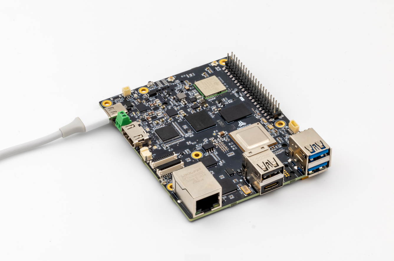
5.1. Board Orientation
Mount the board in your vehicle with the GemStone logo pointing toward the front of the vehicle. This ensures proper sensor orientation and coordinate system alignment.5.2. Status LEDs
The green-red status LEDs located near CSI/DSI ports indicate the flight controller’s current state. Refer to ArduPilot’s documentation for detailed LED patterns and their meanings.5.3. Flight Logs
ArduPilot stores flight logs in/opt/ardupilot/var/log/ using the binary BIN format.
Logs are automatically rotated, with LASTLOG.TXT indicating the most recent log number.
These logs can be analyzed using UAV Log Viewer.
5.4. Peripherals
The 40-pin GPIO header provides access to peripherals, PWM outputs, and communication interfaces.5.4.1. GPIO Pinout
The following table shows the function of each pin in the GPIO header after applying device-tree overlays. The table assumes the board is oriented so that you can see the GemStone logo upright.| 3v3 Power | 3v3 Power | 5v Power | 5v Power |
|---|---|---|---|
| I2C-MCU0 SDA (GPS, ADS1115) | GPIO-2 | 5v Power | 5v Power |
| I2C-MCU0 SCL (GPS, ADS1115) | GPIO-3 | GND | GND |
| UART-MAIN6 RX (GPS) | GPIO-4 | GPIO-14 | PWM-0B (RCOut-2) |
| GND | GND | GPIO-15 | UART-MAIN1 RX (RCIn SBUS) |
| UART-MAIN6 TX (GPS) | GPIO-17 | GPIO-18 | PWM-ECAP2 (RCOut-7) |
| GPIO-27 | GND | GND | |
| GPIO-22 | GPIO-23 | ||
| 3v3 Power | 3v3 Power | GPIO-24 | UART-WKUP0 TX (Telemetry) |
| SPI-MCU0 MOSI | GPIO-10 | GND | GND |
| SPI-MCU0 MISO | GPIO-9 | GPIO-25 | |
| SPI-MCU0 SCLK | GPIO-11 | GPIO-8 | SPI-MCU0 CS0 |
| GND | GND | GPIO-7 | UART-WKUP0 RX (Telemetry) |
| I2C-WKUP0 SDA (Reserved) | GPIO-0 | GPIO-1 | I2C-WKUP0 SCL (Reserved) |
| PWM-0A (RCOut-1) | GPIO-5 | GND | GND |
| PWM-1A (RCOut-3) | GPIO-6 | GPIO-12 | PWM-ECAP0 (RCOut-5) |
| PWM-1B (RCOut-4) | GPIO-13 | GND | GND |
| GPIO-19 | GPIO-16 | PWM-ECAP1 (RCOut-6) | |
| Buzzer | GPIO-26 | GPIO-20 | |
| GND | GND | GPIO-21 |
5.4.2. Device Paths
Linux device paths for each peripheral:| UART-WKUP0 | /dev/ttyS0 |
|---|---|
| UART-MAIN1 | /dev/ttyS3 |
| UART-MAIN6 | /dev/ttyS6 |
| I2C-MCU0 | /dev/i2c-1 |
| SPI-MCU0 CS0 | /dev/spidev0.0 |
| PWM-0A | /sys/class/pwm/pwmchip3/pwm0 |
| PWM-0B | /sys/class/pwm/pwmchip3/pwm1 |
| PWM-1A | /sys/class/pwm/pwmchip5/pwm0 |
| PWM-1B | /sys/class/pwm/pwmchip5/pwm1 |
| PWM-ECAP0 | /sys/class/pwm/pwmchip0/pwm0 |
| PWM-ECAP1 | /sys/class/pwm/pwmchip1/pwm0 |
| PWM-ECAP2 | /sys/class/pwm/pwmchip2/pwm0 |
5.4.3. RC Input
The board supports RC input via the SBUS protocol through the UART-MAIN1 RX (GPIO-15) pin. SBUS is a widely used digital RC protocol that provides reliable communication between your RC receiver and the flight controller.5.4.3.1. Signal Inversion Requirement
SBUS protocol uses an inverted serial signal, which means you must use an external signal inverter circuit between your SBUS receiver and the UART-MAIN1 RX pin. Without this inverter, the board will not be able to read SBUS data correctly. To build the signal inverter circuit, you will need:- 1x NPN transistor (e.g., S9014 TO-92 package)
- 1x 10kΩ resistor
- 1x 1kΩ resistor
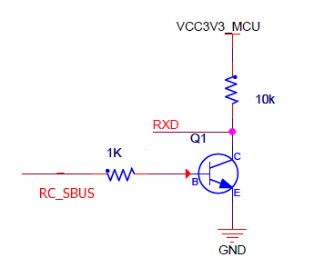
- SBUS receiver output connects through the 1kΩ resistor to the transistor base
- Transistor collector connects to UART-MAIN1 RX pin (GPIO-15)
- 10kΩ pull-up resistor connects between collector and 3v3 VCC
- Transistor emitter connects to GND
5.5. QGroundControl Connection
QGroundControl (QGC) is the recommended ground control station for ArduPilot. You can connect via UDP or serial telemetry.5.5.1. USB-Ethernet Connection (Default)
Connect the Gemstone board to your PC via USB Type-C cable. The board uses USB Gadget API to provide Ethernet-over-USB with automatic IP configuration:- Board IP:
192.168.7.2 - PC IP: Assigned via DHCP (typically
192.168.7.59) - MAVLink Port: UDP broadcast at
192.168.7.255:14550
5.5.2. Serial Telemetry Connection
For wireless telemetry using radio modules:-
Connect telemetry radio to Gemstone board
- Connect telemetry module to board’s UART-WKUP0 pins
-
Connect telemetry radio to PC
- Insert the second radio module to your PC via USB-to-TTL device
- Note the created TTY device (e.g.,
/dev/ttyUSB0)
-
Configure QGroundControl
- Open Application Settings → Comm Links
- Click Add button
- Select the correct serial port and 57600 baud rate
- Save configuration and click Connect button
6. Troubleshooting
6.1. ArduPilot Service Won’t Start
Check service status and logs:6.2. No MAVLink Connection
Verify network configuration from PC:6.3. GPS Not Detected
GPS should be connected to UART-MAIN6 (GPIO-4 and GPIO-17) and I2C-MCU0 (pins GPIO-2 and GPIO-3). Check GPS connection on GPIO header pins and verify configuration:6.4. PWM Outputs or Serial Ports Not Working
Verify device-tree overlays are loaded:/boot/uEnv.txt configuration and reboot the board.