

src/ugv_bringup/config/hardware.yaml.
Pins are written with T3 Gemstone O1 line names ("GPIO22") and PWM channels with module names ("ecap0"); the software
resolves them to the board’s lines by itself.
1. Components
2. Wiring Diagram
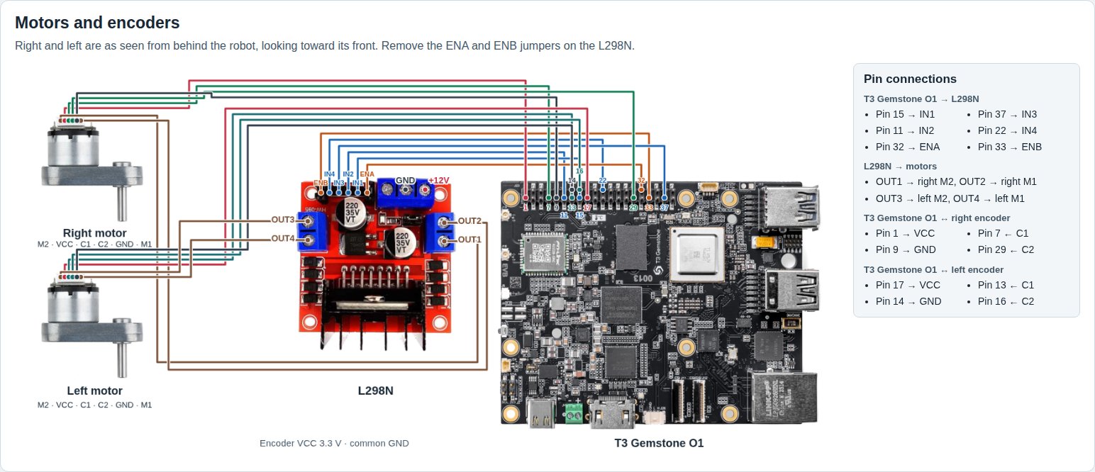
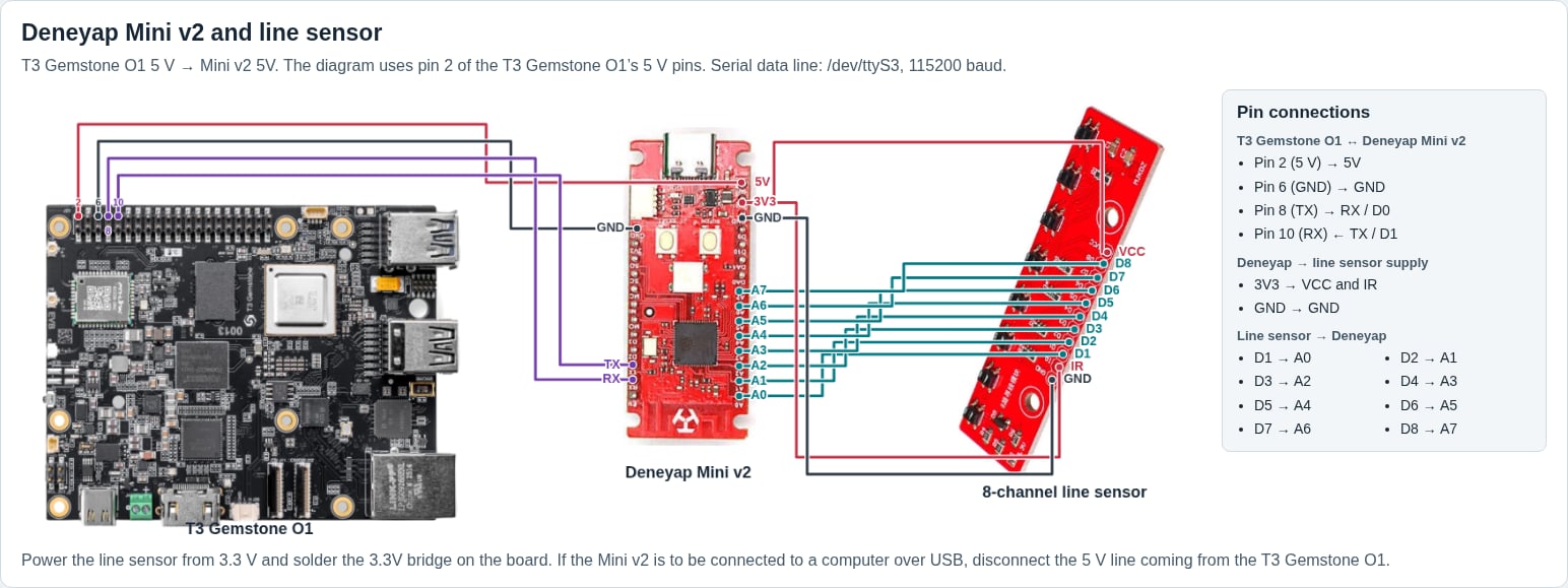
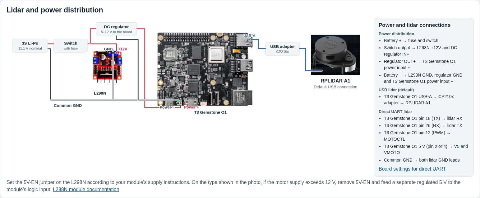
The signal connections reflect thehardware.yaml configuration. The complete wiring diagram is also available as a
PDF.
2.1. Motors and encoders
2.2. Deneyap Mini v2 and line sensor
2.3. Lidar and power distribution
3. 40-Pin Header
The pin numbers in the table are the physical numbers on the board.
T3 Gemstone O1 40-pin connection map for UGV
left / right blocks in hardware.yaml follow this. If the motors are mounted on the other sides, swap the left
and right blocks (together with their direction settings) instead of the wires. To verify this,
hw_check motors spins the left wheel first during the
Field Test.
4. Lidar Connection
The RPLIDAR A1 can be connected in two ways. The connection type is selected from the Lidar panel in the web interface, and the selection is stored on the robot (~/.ugv/lidar_source). The default connection is USB.
- USB (default)
- GPIO (UART)
Plug the lidar into T3 Gemstone O1’s USB port with its own adapter board; no other wiring is needed. The port is found
automatically under
/dev/serial/by-id/, and the adapter drives the lidar motor.The CP210x USB-serial driver may be missing from the minimal T3 Gemstone O1 image. If lsusb shows the adapter but
/dev/ttyUSB0 is not created, follow the driver installation steps on the
Installation page.5. Line Sensor
The sensor in the kit is the Pololu QTR-8A, an 8-channel reflectance sensor array. Each channel is a phototransistor pulled up to VCC: as reflection increases the output voltage drops, and over a black line the output is approximately VCC. The board has no comparator; the outputs are analog. The sensor must be 3–6 mm above the surface.The sensor height directly affects the readings. At a height of 1 cm, 2.7–3.0 V was measured on a white surface and
3.1 V on black; at this height the difference drops to 100 mV, and with the direct GPIO connection every channel
reads 1. Lower the sensor to 3–6 mm above the surface.
hardware.yaml →
line_sensor_node.type.
- Deneyap Mini v2 (default)
- Direct GPIO
With the
type: serial configuration, the Mini v2 reads the eight analog channels in millivolts and sends about 50
readings per second to T3 Gemstone O1’s /dev/ttyS3 UART at 115200 baud. The UART lines of both boards use 3.3 V logic
levels.Sensor → Mini v2Mini v2 → T3 Gemstone O1
- The sensor’s D1–D8 outputs go to the Mini v2’s A0–A7 inputs. Here the Mini v2’s D1 pin is not a sensor input but the UART TX pin going to T3 Gemstone O1.
- Cross TX and RX on the signal connection and connect the GND terminals together.
- The Mini v2’s 5V pin is connected to the USB supply line. Before connecting the Mini v2 to a computer over USB for programming, disconnect the 5 V line coming from T3 Gemstone O1. Deneyap Mini v2 pin definitions
hardware.yaml must contain type: serial, serial.port: /dev/ttyS3 and
serial.baudrate: 115200. For the firmware to upload to the Mini v2, refer to the
Installation page. The same source
code can also be compiled for the Deneyap Kart 1A v2; in that case, follow that board’s pin labels.6. Electrical Warnings
- T3 Gemstone O1 GPIOs are 3.3 V. The encoders are powered from 3V3 in the diagram, so their internal pull-ups also pull to 3.3 V. Do not power the encoders from 5 V.
- Power the line sensor with 3.3 V only and solder the “3.3V” bridge. The IR pin can be left unconnected.
- The lidar is powered with 5 V, but its UART signals are 3.3 V and can be connected directly. Lidar TX → T3 Gemstone O1 RX (pin 26), lidar RX → T3 Gemstone O1 TX (pin 18).
- The ENA/ENB jumpers on the L298N must be removed.
- Set the 5V-EN bridge on the L298N according to the module’s power supply instructions. If the motor supply exceeds 12 V, the 5V-EN bridge must be removed and a separate 5 V must be supplied to the module’s logic input.
- A fully charged 3S battery is 12.6 V; since the L298N drops about 2 V, the motors run slightly below their rated
voltage. Measure
max_wheel_speedwithhw_check sweepduring the Field Test. - The battery, L298N, T3 Gemstone O1 and encoder GNDs must be common.
- Supply T3 Gemstone O1’s power input within its 5–12 V range. Since a fully charged 3S battery reaches 12.6 V, feed the power input through a suitable DC regulator. Battery and Operating Safety