

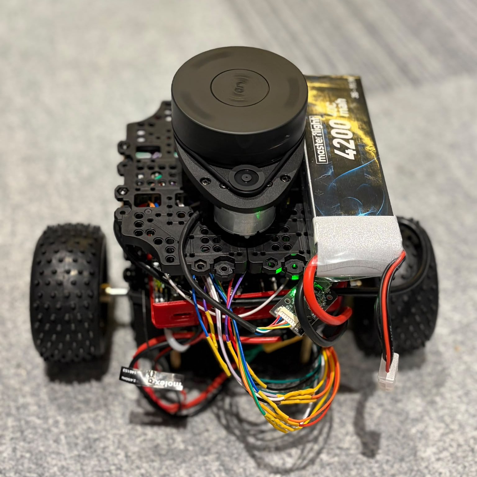
Battery and cable layout
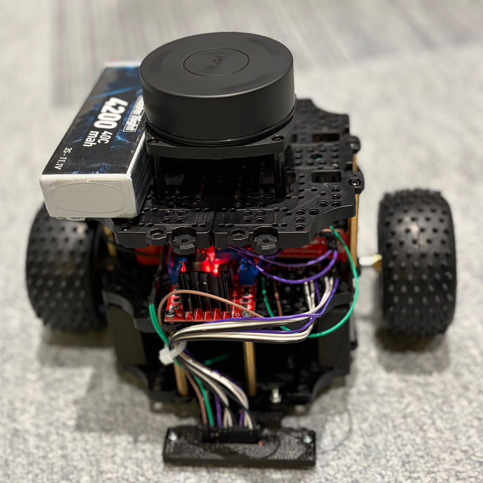
Line sensor and motor driver
1. Introduction
UGV ROS is a differential-drive ground robot based on T3 Gemstone O1. The robot runs Ubuntu 24.04 and ROS 2 Jazzy. It can follow a line, map its surroundings with a lidar and, when Nav2 is enabled, drive to a selected goal on a saved map.- Manual driving uses the keyboard, the on-screen arrow buttons or a gamepad. Wheel speed is measured with encoders, and odometry is fused with the IMU on the board.
- Line following uses an eight-channel analog sensor read through a Deneyap Mini v2. White and black surface measurements are recorded from the web interface.
- Mapping and navigation use an RPLIDAR A1. Maps can be saved, and when Nav2 is enabled a goal can be selected on the map.
2. Components
All pin connections are listed on the Hardware and Wiring page.
3. Web Interface
The UGV Control interface running on the robot is opened from a browser on a computer connected to the same network. ROS does not need to be installed on the computer.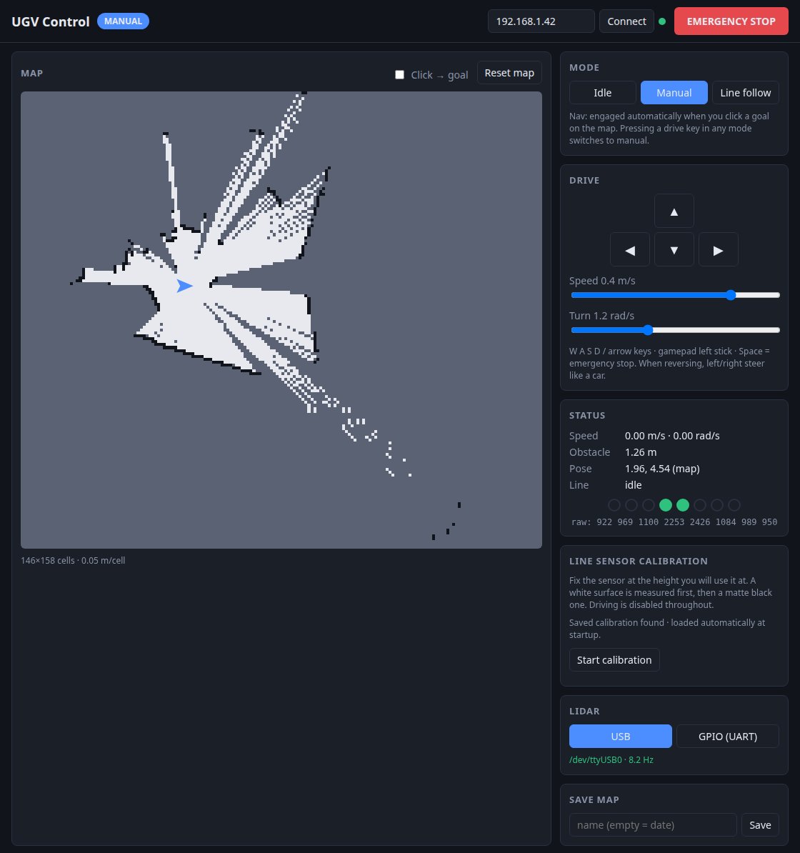
The UGV Control screen with a map imported from a recorded lidar scan and sample sensor values.
To stop driving, use the EMERGENCY STOP button or the Space key.
4. Getting Started
1
Install the operating system and the UGV software
Write the Ubuntu 24.04 image to T3 Gemstone O1, install ROS 2 Jazzy and the dependencies, and build the workspace.
Then upload the line sensor firmware to the Deneyap Mini v2 and enable the PWM/UART overlays.
Installation
2
Connect the hardware
With the power off, complete the motor, encoder, line sensor and lidar connections.
Hardware and Wiring
3
Read the safety rules
Read the battery and operating safety rules before the first drive.
Battery and Operating Safety
4
Run the field test
With the wheels off the ground, verify the motor directions, encoders, IMU and lidar step by step.
Field Test
5
Start and use the robot
Start the robot, open the web interface, calibrate the line sensor and build a map.
Usage
5. Technical References
Architecture
ROS 2 packages, topics, services and driving modes
Simulation
Mapping, navigation and line following in Gazebo, without the robot
Network Connection
Connecting the robot to a new Wi-Fi network and finding its IP address
PWM
T3 Gemstone O1 PWM channels and overlay configuration
IMU
The onboard ICM-20948 sensor