By the end of this section, you will have gained experience in the following areas:
- How to connect a CSI camera to the Gemstone O1 development board.
- Adding overlays.
What is CSI?
CSI (Camera Serial Interface) is a serial bus designed for high-resolution cameras in mobile devices and embedded systems.
This interface was developed by the MIPI (Mobile Industry Processor Interface) Alliance and enables high-speed, reliable transfer of image and video data between the processor and the camera sensor.
It is commonly preferred in cameras used in smartphones, drones, and mini handheld computers.
Steps
Making the Cable Connection
The cable between the camera and the Gemstone O1 development board must be connected correctly.
Adding an Overlay
The relevant overlay must be added to the uEnv.txt file located in the boot partition for the CSI camera to work.
Board Reboot
After completing all these steps, simply reboot the development board.
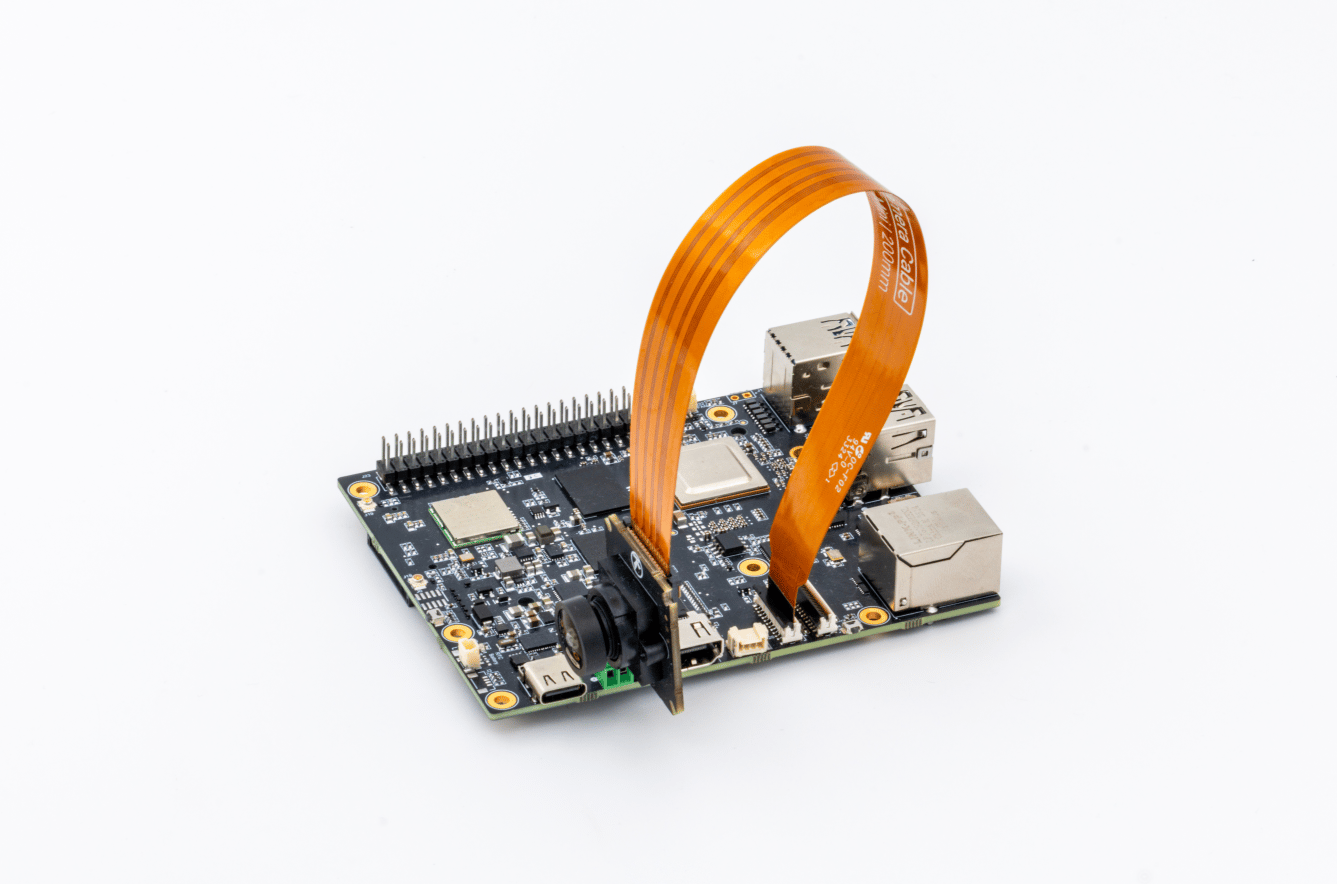
1. Making the Cable Connection
To properly connect the cable between the camera and the Gemstone O1 development board, you must make a connection as shown in the photo below.
You can connect the CSI cable to either socket; the important thing here is that you must add the overlay that activates the CSI of the socket you plugged into.
The part of the cable containing the copper wires should face the white part of the socket.
The connector farther from the Ethernet socket is CSI0, while the connector closer to it is CSI1.
2. Adding an Overlay
You can view the overlays of supported cameras using the following command.
ls /boot/overlays/ | grep "csi"
uEnv.txt file located in the boot directory using the nano text editor from the terminal interface.
Since we are using the command with sudo, it will ask for a password. If you haven’t changed it, you should use the password you set when writing the image with Gem-Imager.
uEnv.txt file will contain definitions like these.
firstboot=0
overlays=k3-am67a-t3-gem-o1-spidev0-2cs.dtbo k3-am67a-t3-gem-o1-i2c1-400000.dtbo

bootpart=1:1
initrdaddr=0x90000000
fdtoverlayaddr=0x89000000
get_kern_mmc=load mmc ${bootpart} ${loadaddr} Image
get_fdt_mmc=load mmc ${bootpart} ${fdtaddr} k3-am67a-t3-gem-o1.dtb;fdt addr ${fdtaddr};fdt resize 8192
get_initrd_mmc=load mmc ${bootpart} ${initrdaddr} gemstone-image-rd-t3-gem-o1.cpio.gz
get_overlays=for o in ${overlays}; do load mmc ${bootpart} ${fdtoverlayaddr} overlays/${o};fdt apply ${fdtoverlayaddr}; done
args_mmc=setenv bootargs console=${console} ${optargs} root=/dev/mmcblk1p2 rw rootfstype=btrfs bootpart=/dev/mmcblk1p1 firstboot=${firstboot} init_fatal_sh=1
boot_mmc=run get_kern_mmc;run get_fdt_mmc;run get_overlays;run get_initrd_mmc;booti ${loadaddr} ${initrdaddr}:${filesize} ${fdtaddr}
distro_bootcmd=run args_mmc;run boot_mmc
overlays= leaving a space. For example, when you connect the IMX219 camera to the CSI0 connector (the connector that is far from the Ethernet port).
k3-am67a-t3-gem-o1-csi0-imx219.dtbo
uEnv.txt file will look like this. You must place the appropriate file name in the <file-name> section.
firstboot=0
overlays=k3-am67a-t3-gem-o1-spidev0-2cs.dtbo k3-am67a-t3-gem-o1-i2c1-400000.dtbo <file-name>

bootpart=1:1
initrdaddr=0x90000000
fdtoverlayaddr=0x89000000
get_kern_mmc=load mmc ${bootpart} ${loadaddr} Image
get_fdt_mmc=load mmc ${bootpart} ${fdtaddr} k3-am67a-t3-gem-o1.dtb;fdt addr ${fdtaddr};fdt resize 8192
get_initrd_mmc=load mmc ${bootpart} ${initrdaddr} gemstone-image-rd-t3-gem-o1.cpio.gz
get_overlays=for o in ${overlays}; do load mmc ${bootpart} ${fdtoverlayaddr} overlays/${o};fdt apply ${fdtoverlayaddr}; done
args_mmc=setenv bootargs console=${console} ${optargs} root=/dev/mmcblk1p2 rw rootfstype=btrfs bootpart=/dev/mmcblk1p1 firstboot=${firstboot} init_fatal_sh=1
boot_mmc=run get_kern_mmc;run get_fdt_mmc;run get_overlays;run get_initrd_mmc;booti ${loadaddr} ${initrdaddr}:${filesize} ${fdtaddr}
distro_bootcmd=run args_mmc;run boot_mmc
3. Rebooting the Board
The development board should be restarted using the reboot command.
4. Running the gem-camera-setup Script
The camera connected to the board should be initialized via the following command.
sudo /usr/local/bin/gem-camera-setup
5. Camera Settings
Initially, the following command is used to establish proper communication between the kernel driver of a camera sensor and user space applications.
When the command is executed, the video output of the IMX219 camera sensor is set to a resolution of 640x480 and the SRGGB8 format. This setting ensures that applications that will use this data stream in the next step (e.g., a camera application or gstreamer) receive the correct data.
media-ctl -V '"imx219 5-0010":0[fmt:SRGGB8_1X8/640x480 field:none]'
v4l2-ctl -d /dev/video-imx219-cam0 --list-formats
You should enter the device specified in the output of the gem-camera-setup script in the /dev/video-imx219-cam0 section.
v4l2-ctl -d /dev/v4l-subdev2 --set-ctrl=digital_gain=2048
v4l2-ctl -d /dev/v4l-subdev2 --set-ctrl=analogue_gain=230
v4l2-ctl -d /dev/v4l-subdev2 --set-ctrl=exposure=1750
v4l2-ctl -d /dev/v4l-subdev2 --set-ctrl=digital_gain=1000
v4l2-ctl -d /dev/v4l-subdev2 --set-ctrl=analogue_gain=100
v4l2-ctl -d /dev/v4l-subdev2 --set-ctrl=exposure=1000
6. Taking Photos
You can capture an image in .jpg format by running the following command.
gst-launch-1.0 -v v4l2src num-buffers=5 device=/dev/video-imx219-cam0 io-mode=dmabuf ! \
    video/x-bayer, width=1920, height=1080, framerate=30/1, format=rggb ! \
    bayer2rgb ! videoconvert ! jpegenc ! \
    multifilesink location="imx219-image-%d.jpg"
7. Video Recording
You can capture a video recording (100 frames) in .mp4 format by running the following command.
gst-launch-1.0 v4l2src device=/dev/video-imx219-cam0 num-buffers=100 io-mode=dmabuf ! \
    video/x-bayer, width=640, height=480, format=rggb,depth=8 ! \
    queue ! bayer2rgb ! queue ! videoconvert ! video/x-raw,format=NV12 ! \
    queue ! v4l2h264enc ! queue !  h264parse ! mp4mux  ! filesink location=t3-gem-o1.mp4