By the end of this section, you will have gained experience in the following areas:
- How to connect a DSI touchscreens to the Gemstone O1 development board.
- Adding overlays.
What is DSI?
DSI (Display Serial Interface) is a serial bus designed for high-resolution displays used in mobile devices and embedded systems.
This interface was developed by the MIPI (Mobile Industry Processor Interface) Alliance and enables high-speed data transfer with low power consumption.
It is ideal for establishing communication between LCD and OLED panels and processors, particularly in smartphones, tablets, and portable devices.
Steps
Making the Cable Connection
The cable between the screen and the Gemstone O1 development board must be connected correctly.
Adding an Overlay
The relevant overlay must be added to the uEnv.txt file located in the boot partition for the DSI screen to function.
Board Reboot
After completing all these steps, simply reboot the development board.
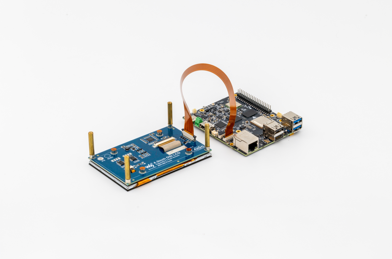
1. Making the Cable Connection
To properly connect the cable between the screen and the Gemstone O1 development board, you must connect it to the DSI0 connector (the one near the Ethernet socket) as shown in the photo below.
The part of the cable containing the copper wires should face the white part of the socket.
2. Adding an Overlay
Open the uEnv.txt file located in the boot directory using the nano text editor from the terminal interface.
Since we are using the command with sudo, it will ask for a password. If you haven’t changed it, you should use the password you set when writing the image with Gem-Imager.
uEnv.txt file will contain definitions like these.
firstboot=0
overlays=k3-am67a-t3-gem-o1-spidev0-2cs.dtbo k3-am67a-t3-gem-o1-i2c1-400000.dtbo

bootpart=1:1
initrdaddr=0x90000000
fdtoverlayaddr=0x89000000
get_kern_mmc=load mmc ${bootpart} ${loadaddr} Image
get_fdt_mmc=load mmc ${bootpart} ${fdtaddr} k3-am67a-t3-gem-o1.dtb;fdt addr ${fdtaddr};fdt resize 8192
get_initrd_mmc=load mmc ${bootpart} ${initrdaddr} gemstone-image-rd-t3-gem-o1.cpio.gz
get_overlays=for o in ${overlays}; do load mmc ${bootpart} ${fdtoverlayaddr} overlays/${o};fdt apply ${fdtoverlayaddr}; done
args_mmc=setenv bootargs console=${console} ${optargs} root=/dev/mmcblk1p2 rw rootfstype=btrfs bootpart=/dev/mmcblk1p1 firstboot=${firstboot} init_fatal_sh=1
boot_mmc=run get_kern_mmc;run get_fdt_mmc;run get_overlays;run get_initrd_mmc;booti ${loadaddr} ${initrdaddr}:${filesize} ${fdtaddr}
distro_bootcmd=run args_mmc;run boot_mmc
l /boot/overlays/ | grep "dsi"
overlays= line, leaving a space.
The final version of the uEnv.txt file will look like this. You must place the appropriate file name in the <file-name> section.
firstboot=0
overlays=k3-am67a-t3-gem-o1-spidev0-2cs.dtbo k3-am67a-t3-gem-o1-i2c1-400000.dtbo <file-name>

bootpart=1:1
initrdaddr=0x90000000
fdtoverlayaddr=0x89000000
get_kern_mmc=load mmc ${bootpart} ${loadaddr} Image
get_fdt_mmc=load mmc ${bootpart} ${fdtaddr} k3-am67a-t3-gem-o1.dtb;fdt addr ${fdtaddr};fdt resize 8192
get_initrd_mmc=load mmc ${bootpart} ${initrdaddr} gemstone-image-rd-t3-gem-o1.cpio.gz
get_overlays=for o in ${overlays}; do load mmc ${bootpart} ${fdtoverlayaddr} overlays/${o};fdt apply ${fdtoverlayaddr}; done
args_mmc=setenv bootargs console=${console} ${optargs} root=/dev/mmcblk1p2 rw rootfstype=btrfs bootpart=/dev/mmcblk1p1 firstboot=${firstboot} init_fatal_sh=1
boot_mmc=run get_kern_mmc;run get_fdt_mmc;run get_overlays;run get_initrd_mmc;booti ${loadaddr} ${initrdaddr}:${filesize} ${fdtaddr}
distro_bootcmd=run args_mmc;run boot_mmc
3. Rebooting the Development Board
The development board should be restarted using the reboot command.