PWM Interfaces
The PWM interfaces available on the T3-GEM-O1 board are listed in the table below.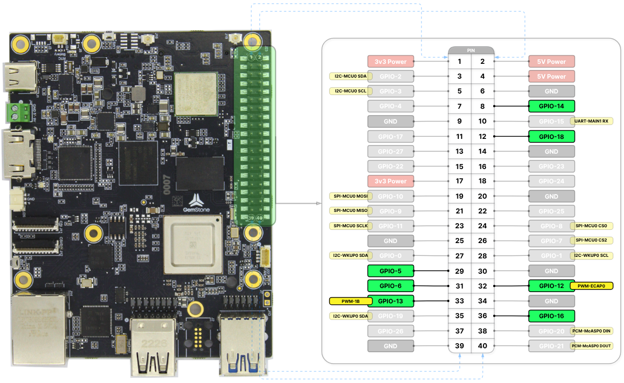
| GPIO | |||
|---|---|---|---|
| PWM-ECAP0 | pwmchip0/pwm0 | GPIO-12 | k3-am67a-t3-gem-o1-pwm-ecap0-gpio12.dtso |
| PWM-ECAP1 | pwmchip1/pwm0 | GPIO-16 | k3-am67a-t3-gem-o1-pwm-ecap1-gpio16.dtso |
| PWM-ECAP2 | pwmchip2/pwm0 | GPIO-18 | k3-am67a-t3-gem-o1-pwm-ecap2-gpio18.dtso |
| PWM-0A | pwmchip3/pwm0 | GPIO-5 | k3-am67a-t3-gem-o1-pwm-epwm0-gpio5.dtso |
| PWM-0B | pwmchip3/pwm1 | GPIO-14 | k3-am67a-t3-gem-o1-pwm-epwm0-gpio14.dtso |
| PWM-1A | pwmchip5/pwm0 | GPIO-6 | k3-am67a-t3-gem-o1-pwm-epwm1-gpio6.dtso |
| PWM-1B | pwmchip5/pwm1 | GPIO-13 | k3-am67a-t3-gem-o1-pwm-epwm1-gpio13.dtso |
| PWM-2A | pwmchip7/pwm0 | FAN header | k3-am67a-t3-gem-o1-gpio-fan.dtso |
To enable PWM-0A and PWM-0B together:
k3-am67a-t3-gem-o1-pwm-epwm0-gpio5-gpio14.dtsoTo enable PWM-1A and PWM-1B together: k3-am67a-t3-gem-o1-pwm-epwm1-gpio6-gpio13.dtsooverlays variable
in the /boot/uEnv.txt file. Detailed information about overlays can be found in the
Device Tree section.
When all overlays are enabled, there are 8 separate PWM interfaces available: 1 from the FAN header
and 7 from the 40-pin header.
PWM Usage
PWM chips can be accessed via the/sys/class/pwm directory. Before using a PWM device, an export operation
must be performed. For example, referring to the table above, the PWM-ECAP0 interface corresponds to the
pwm0 device of the pwmchip0 chip. After executing the following command, the /sys/class/pwm/pwmchip0/pwm0
device will be created. The reason for writing echo 0 is that it corresponds to pwm0, i.e., device number 0.
PWM-0B interface is to be used, the pwm1 device of the pwmchip3 chip should be activated
as shown in the following command. The reason for writing echo 1 is that it corresponds to pwm1, i.e.,
device number 1.
export operation, the period and duty_cycle variables (in nanoseconds) can be set to desired
values as shown in the example below. Once the enable variable is set to 1, the PWM output can be obtained.
enable variable to 0.
unexport operation can be performed. This will remove the
device from the system. The reason for writing echo 0 is that it corresponds to pwm0, i.e., device number 0.