1. Boot Diagram
The flow chart specified below is for the Gemstone O1 development board, but a similar structure is found in many ARM-based embedded Linux development boards.1.1. ROM Bootloader (RBL)
The primary purpose of the RBL (ROM Bootloader), which is often distributed only as a compiled program without source code by manufacturers, is to perform hardware health checks and initialization etc., when the board is first powered on, and then transition to the second bootloader called SBL (Secondary Bootloader), whose source code can be modified. Where the SBL is read from and started is determined by the RBL from the Bootmode switches.1.2. Secondary Bootloader (SBL)
The purpose of the Secondary Boot Loader on T3-GEM-O1 development boards is to start the more advanced bootloader called U-Boot and to enable writing images to eMMC via the Gemstone Imager application. U-Boot is often preferred in embedded boards containing the Linux Kernel. While pre-loaders like SBL can perform more basic level initialization operations, U-Boot has much more advanced features. For example, U-Boot has its own Terminal/Console interface and many drivers not available in SBL, allowing for more advanced customizations.1.3. U-Boot
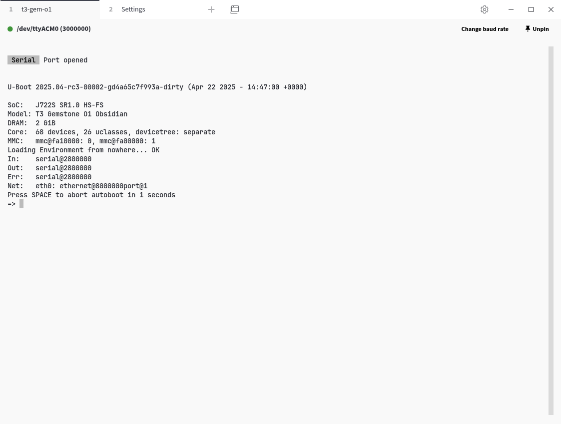
U-Boot, which takes control of the development board after SBL, activates the drivers of the relevant hardware according to the configurations defined in the Device Tree and executes a set of predefined commands to load components like the Linux Kernel and Initrd into RAM, handing over control to the Linux Kernel.1.3.1. U-Boot Console Exercises
1.4. Linux Kernel
It loads the drivers for the hardware defined in the Device Tree. Then, if any, it starts the initrd/initramfs and runs theinit program found in the rootfs.
1.5. Initial RAM Disk (Initrd)
It is a temporary filesystem located in RAM that performs intermediate tasks such as loading various kernel modules, decrypting the disk, performing software updates, etc., before the rootfs is started.1.6. Root Filesystem (Rootfs)
After the initrd finishes its operations, it mounts the filesystem called rootfs, which contains system and user programs, libraries, and various configuration files, to the/ directory.
Then the kernel runs the init program located in the rootfs at /init, /sbin/init, or a similar directory.
This program loads drivers for some hardware (kernel modules), system services (services such as network
connection, time synchronization, package update, and bluetooth) and starts the desktop environment (gnome, kde, xfce).
2. MCU Software Development
The tools required to compile MCU projects are listed below.- Texas Instruments Processor SDK RTOS J722S
- Texas Instruments Sysconfig
- Texas Instruments Code Generation Tools C7000
- Texas Instruments Code Generation Tools ARM LLVM
2.1. Download the sample projects with Git clone
2.2. Install the necessary tools and libraries for compilation
2.3. Create a template project
Themcu project in the t3gemstone/examples repo contains sample
projects running on two R5F real-time cores and two C7x DSP cores. Similar examples can be found in
the build/ti/ti-processor-sdk-rtos-j722s-evm-10_01_00_04/mcu_plus_sdk_j722s_10_01_00_22/examples directory.
It is recommended to find an example project suitable for your purpose, copy it to the mcu project directory,
and develop on it.
Under each sample project, there are subdirectories for different cores.
For example, the hello_world project has the following directories.
c75ss0-0_freertosc75ss1-0_freertosmain-r5fss0-0_freertosmcu-r5fss0-0_freertos
MCU_TARGETS variable in the .env file. Add the absolute or
relative path of the makefile directory of the project you want to compile to the MCU_TARGETS variable. Below
is an example for the mcu-r5fss0-0_freertos core of the hello_world project.
2.4. Configure peripherals with SysConfig
SysConfig is a configuration tool developed by Texas Instruments (TI). It is used in TI’s microcontroller (MCU) and processor-based development environments. Its main purpose is to allow the configuration of hardware and software settings visually. Instead of writing complex initialization code directly, it allows system configuration via a GUI by clicking options. Main features:- Pin Muxing: Determines which pin will serve which function (UART, SPI, GPIO, etc.).
- Peripheral Settings: Configures peripherals like UART, I2C, Timer, ADC.
- Driver and RTOS configuration: Enables TI-Drivers or FreeRTOS components.
- Automatic Code Generation: Automatically generates C source files (.c, .h) based on the settings made.
- Error prevention: Detects inappropriate pin or module combinations and warns.
.syscfg file.
The SysConfig GUI tool is used to add new peripherals or change the Pin Mux settings of existing ones.
To launch SysConfig for an MCU project:
- Change the
SYSCONFIG_TARGETvariable to the desired project.- You can edit this variable inside the
.envfile or - Pass it as an environment variable to the
taskprogram.
- You can edit this variable inside the
Ctrl + S shortcut key, you can close the SysConfig interface.
2.5. Build the project
2.6. Upload the compiled project to the development board
2.7. Run the compiled project
The.out files to be loaded to the cores via Remoteproc must be copied under the /lib/firmware directory
with predefined names. The firmware name for each core is given in the table below.
| Core | Firmware |
|---|---|
| mcu-r5fss0-0 | j722s-mcu-r5f0_0-fw |
| main-r5fss0-0 | j722s-main-r5f0_0-fw |
| c7xss0-0 | j722s-c71_0-fw |
| c7xss1-0 | j722s-c71_1-fw |
head /sys/class/remoteproc/remoteproc*/firmware command. This needs to be checked because after each boot,
the cores can correspond to different remoteproc devices.
2.8. Running the Compiled Project at the U-Boot Stage
As seen in the diagram in the Boot Diagram section, when using the execution method described in the previous section, for the MCU application to run, Linux must complete its startup process and load and start the core software. This process can cause unwanted delays in some applications. This delay can be prevented by starting the remote cores at the bootloader (U-Boot) stage.- First, the compiled application is copied to the
/boot/mcu-fw/directory. - In the
/boot/uEnv.txtfile, the necessary parameter is defined using the table below, depending on which core the compiled application belongs to.
| Core | Variable Name |
|---|---|
| main-r5fss0-0 | main_r5f_firmware_name |
| mcu-r5fss0-0 | mcu_r5f_firmware_name |
| wkup-r5fss0-0 | wkup_r5f_firmware_name |
| c7xss0-0 | c7x0_dsp_firmware_name |
| c7xss1-0 | c7x1_dsp_firmware_name |
blink_main_r5 is desired to run on the main-r5fss0-0 core at the U-Boot
stage, first the application is copied to the /boot/mcu-fw directory as shown below.
/boot/uEnv.txt file.
blink_main_r5 application will be started directly at the bootloader stage, without waiting for Linux to start.
3. Sharing Resources Between Cores
Due to the AM67 being a multi-core processor, the resources it possesses must be shared among these cores. For example, themain_uart1 uart peripheral cannot be used simultaneously by both Linux (A53 cores) and the
main-r5fss0-0 core. If this UART peripheral is to be used by the MCU, it must be indicated that it is not used by Linux.
3.1. Default Resource Allocation Table
The table below provides information such as which SOC pins the pins on the HAT correspond to, which peripherals they can be used as (Pinmux), whether they are used by default by Linux, if so for what purpose, and how this can be disabled.Resource Table
Resource Table
| HAT Pin Name | SoC Pin Name | Pinmux | Enabled in Linux by Default? | Purpose in Linux | How to Disable |
|---|---|---|---|---|---|
| GPIO-0 | D11 | 0 → WKUP_I2C0_SDA 7 → MCU_GPIO0_20 | Yes | I2C SDA for communication with EEPROM, RTC, and PMIC | Must be disabled via Device-tree (wkup_i2c0). |
| GPIO-1 | B9 | 0 → WKUP_I2C0_SCL 7 → MCU_GPIO0_19 | Yes | I2C SCL for communication with EEPROM, RTC, and PMIC | Must be disabled via Device-tree (wkup_i2c0). |
| GPIO-2 | E11 | 0 → MCU_I2C0_SDA 7 → MCU_GPIO0_18 | No | I2C SDA for Waveshare Touchscreen | - k3-am67a-t3-gem-o1-dsi-waveshare-7inch-h-panel.dtbo - k3-am67a-t3-gem-o1-dsi-waveshare-7inch-panel.dtbo |
| GPIO-3 | B13 | 0 → MCU_I2C0_SCL 7 → MCU_GPIO0_17 | No | I2C SCL for Waveshare Touchscreen | - k3-am67a-t3-gem-o1-dsi-waveshare-7inch-h-panel.dtbo - k3-am67a-t3-gem-o1-dsi-waveshare-7inch-panel.dtbo |
| GPIO-4 | W26 | 0 → GPMC0_WAIT1 1 → VOUT0_EXTPCLKIN 2 → GPMC0_A21 3 → UART6_RXD 4 → AUDIO_EXT_REFCLK2 7 → GPIO0_38 8 → EQEP2_I | Yes | UART RX for Bluetooth | - k3-am67a-t3-gem-o1-uart-ttys6.dtbo - Must be disabled via Device-tree (main_uart6) |
| GPIO-5 | B20 | 0 → SPI0_CS0 2 → EHRPWM0_A 7 → GPIO1_15 | No | General Purpose PWM | - k3-am67a-t3-gem-o1-pwm-epwm0-gpio5.dtbo - k3-am67a-t3-gem-o1-pwm-epwm0-gpio14.dtbo - k3-am67a-t3-gem-o1-pwm-epwm0-gpio5-gpio14.dtbo |
| GPIO-6 | D20 | 0 → SPI0_CLK 1 → CP_GEMAC_CPTS0_TS_SYNC 2 → EHRPWM1_A 7 → GPIO1_17 | Yes | General Purpose PWM | - k3-am67a-t3-gem-o1-pwm-epwm1-gpio6.dtbo - k3-am67a-t3-gem-o1-pwm-epwm1-gpio13.dtbo - k3-am67a-t3-gem-o1-pwm-epwm1-gpio6-gpio13.dtbo |
| GPIO-7 | B3 | 0 → WKUP_UART0_RXD 2 → MCU_SPI0_CS2 7 → MCU_GPIO0_9 | Yes | - SPI Chip Select 2 for Linux spidev - Wakeup Domain UART0 Rx | - k3-am67a-t3-gem-o1-spidev0-1cs.dtbo - k3-am67a-t3-gem-o1-spidev0-2cs.dtbo - k3-am67a-t3-gem-o1-uart-ttys0.dtbo |
| GPIO-8 | C12 | 0 → MCU_SPI0_CS0 4 → WKUP_TIMER_IO1 7 → MCU_GPIO0_0 | Yes | SPI Chip Select 0 for Linux spidev | - k3-am67a-t3-gem-o1-spidev0-1cs.dtbo - k3-am67a-t3-gem-o1-spidev0-2cs.dtbo |
| GPIO-9 | C11 | 0 → MCU_SPI0_D1 7 → MCU_GPIO0_4 | Yes | - SPI DATA1 for BMP390 Pressure Sensor and ICM20948 IMU - SPI DATA1 for Linux spidev (configurable as MOSI or MISO) | Must be disabled via Device-tree (mcu_spi0). |
| GPIO-10 | B12 | 0 → MCU_SPI0_D0 7 → MCU_GPIO0_3 | Yes | - SPI DATA0 for BMP390 Pressure Sensor and ICM20948 IMU - SPI DATA0 for Linux spidev (configurable as MOSI or MISO) | Must be disabled via Device-tree (mcu_spi0). |
| GPIO-11 | A9 | 0 → MCU_SPI0_CLK 7 → MCU_GPIO0_2 | No | SPI Clock for Linux spidev | Must be disabled via Device-tree (mcu_spi0). |
| GPIO-12 | C20 | 0 → SPI0_CS1 1 → CP_GEMAC_CPTS0_TS_COMP 2 → EHRPWM0_B 3 → ECAP0_IN_APWM_OUT 5 → MAIN_ERRORn 7 → GPIO1_16 9 → EHRPWM_TZn_IN5 | Yes | General Purpose PWM | - k3-am67a-t3-gem-o1-pwm-ecap0-gpio12.dtbo |
| GPIO-13 | E19 | 0 → SPI0_D0 1 → CP_GEMAC_CPTS0_HW1TSPUSH 2 → EHRPWM1_B 7 → GPIO1_18 | Yes | General Purpose PWM | - k3-am67a-t3-gem-o1-pwm-epwm1-gpio13.dtbo - k3-am67a-t3-gem-o1-pwm-epwm1-gpio6-gpio13.dtbo |
| GPIO-14 | F24 | 0 → MCASP0_ACLKR 1 → SPI2_CLK 2 → UART1_TXD 6 → EHRPWM0_B 7 → GPIO1_14 8 → EQEP1_I | Yes | - Used as Linux serial device /dev/ttyS3. - Can be configured as General Purpose PWM via overlay. | - k3-am67a-t3-gem-o1-pwm-epwm0-gpio5.dtbo - k3-am67a-t3-gem-o1-pwm-epwm0-gpio14.dtbo - k3-am67a-t3-gem-o1-pwm-epwm0-gpio5-gpio14.dtbo - Must be disabled via Device-tree (main_uart1). |
| GPIO-15 | C27 | 0 → MCASP0_AFSR 1 → SPI2_CS0 2 → UART1_RXD 6 → EHRPWM0_A 7 → GPIO1_13 8 → EQEP1_S | Yes | - Used as Linux serial device /dev/ttyS3. | Must be disabled via Device-tree (main_uart1). |
| GPIO-16 | A25 | 0 → MCASP0_AXR3 1 → SPI2_D0 2 → UART1_CTSn 3 → UART6_RXD 5 → ECAP1_IN_APWM_OUT 7 → GPIO1_7 8 → EQEP0_A | No | General Purpose PWM | - k3-am67a-t3-gem-o1-pwm-ecap1-gpio16.dtbo |
| GPIO-17 | A26 | 0 → MCASP0_AXR2 1 → SPI2_D1 2 → UART1_RTSn 3 → UART6_TXD 5 → ECAP2_IN_APWM_OUT 7 → GPIO1_8 8 → EQEP0_B | Yes | UART TX for Bluetooth | - k3-am67a-t3-gem-o1-uart-ttys6.dtbo - Must be disabled via Device-tree (main_uart6). |
| GPIO-18 | D25 | 0 → MCASP0_ACLKX 1 → SPI2_CS1 2 → ECAP2_IN_APWM_OUT 7 → GPIO1_11 8 → EQEP1_A | No | General Purpose PWM | - k3-am67a-t3-gem-o1-pwm-ecap2-gpio18.dtbo |
| GPIO-19 | C26 | 0 → MCASP0_AFSX 1 → SPI2_CS3 2 → AUDIO_EXT_REFCLK1 7 → GPIO1_12 8 → EQEP1_B | No | - | - |
| GPIO-20 | F23 | 0 → MCASP0_AXR0 2 → AUDIO_EXT_REFCLK0 6 → EHRPWM1_B 7 → GPIO1_10 8 → EQEP0_I | No | - | - |
| GPIO-21 | B25 | 0 → MCASP0_AXR1 1 → SPI2_CS2 2 → ECAP1_IN_APWM_OUT 5 → MAIN_ERRORn 6 → EHRPWM1_A 7 → GPIO1_9 8 → EQEP0_S | Yes | Cooling Fan Control | - k3-am67a-t3-gem-o1-gpio-fan.dtbo |
| GPIO-22 | R27 | 0 → GPMC0_CSn0 1 → I2C4_SCL 3 → MCASP2_AXR14 6 → TRC_DATA15 7 → GPIO0_41 | No | - | - |
| GPIO-23 | B5 | 0 → MCU_UART0_CTSn 1 → MCU_TIMER_IO0 3 → MCU_SPI1_D0 7 → MCU_GPIO0_7 | No | - | - |
| GPIO-24 | C8 | 0 → WKUP_UART0_TXD 2 → MCU_SPI1_CS2 8 → MCU_GPIO0_10 | No | Wake Up Domain UART0 Tx | - k3-am67a-t3-gem-o1-uart-ttys0.dtbo |
| GPIO-25 | P21 | 0 → GPMC0_CSn1 1 → I2C4_SDA 3 → MCASP2_AXR15 6 → TRC_DATA16 7 → GPIO0_42 | No | - | - |
| GPIO-26 | P26 | 0 → GPMC0_BE1n 3 → MCASP2_AXR12 6 → TRC_DATA11 7 → GPIO0_36 | No | - | - |
| GPIO-27 | N22 | 0 → GPMC0_OEn_REn 2 → MCASP1_AXR1 6 → TRC_DATA8 7 → GPIO0_33 | No | - | - |
To Disable for the pin to be disabled. The files listed in this column
as k3-am67a-t3-gem-o1-xxxxxx.dtbo are called device-tree overlay files, which inform Linux how to use the specified
peripheral.
To disable the relevant settings, open the /boot/uEnv.txt file and remove this file from the variable
named overlays. For some pins, the To Disable column contains instructions other than overlays,
such as Must be disabled via Device-tree. (mcu_spi0). To disable these;
- Clone the https://github.com/t3gemstone/devicetrees repo.
- Open the
src/arm64/ti/k3-am67a-t3-gem-o1.dtsfile and add the following code snippet with the necessary modifications. - Run the
makecommand in the repo directory to compile the device-tree. - Back up the old device-tree with the command
$ sudo mv /boot/k3-am67a-t3-gem-o1.dtb /boot/k3-am67a-t3-gem-o1.dtb.bak. - Copy the resulting
src/arm64/ti/k3-am67a-t3-gem-o1.dtbfile from the compilation to/boot/. - Reboot the board and test if it works.
If an undesirable situation occurs as a result of the above operations, the backed-up device-tree can be restored
with the command
$ sudo cp /boot/k3-am67a-t3-gem-o1.dtb.bak /boot/k3-am67a-t3-gem-o1.dtb.mcu_spi0 will now be available for use by the mcu cores. However,
the Usage Purpose in Linux section in the table indicates that it is
- Used for BMP390 pressure and ICM20948 imu spi. Therefore, access to these peripherals from Linux will be
closed and they will need to be driven by the MCU.
3.2. Example Scenario: Driving a Servo Motor from the MCU with PWM
In a scenario where we need to drive an SG90 model servo motor from an MCU core, we must first select a PWM pin on the HAT pins. For example, let’s select theGPIO-12 pin. Looking at the table, we can see that this pin is
in use by Linux. To disable this pin in Linux, when we look at the To Disable column, we see that there is only
one overlay file. To disable it, we open the /boot/uEnv.txt file and check the overlays variable.
k3-am67a-t3-gem-o1-pwm-ecap0-gpio12.dtbo file specified in the table. We delete it,
and the overlays variable becomes as follows.