All examples will be performed via the Terminal/Console after establishing a serial port connection, so it is assumed that you have read the explanations about Terminal usage in the Quick Start section. You may choose one of the methods described in the relevant section: connecting to the Desktop image via a browser, connecting via SSH/Ethernet, or connecting via the console over the serial port.
Power Connection
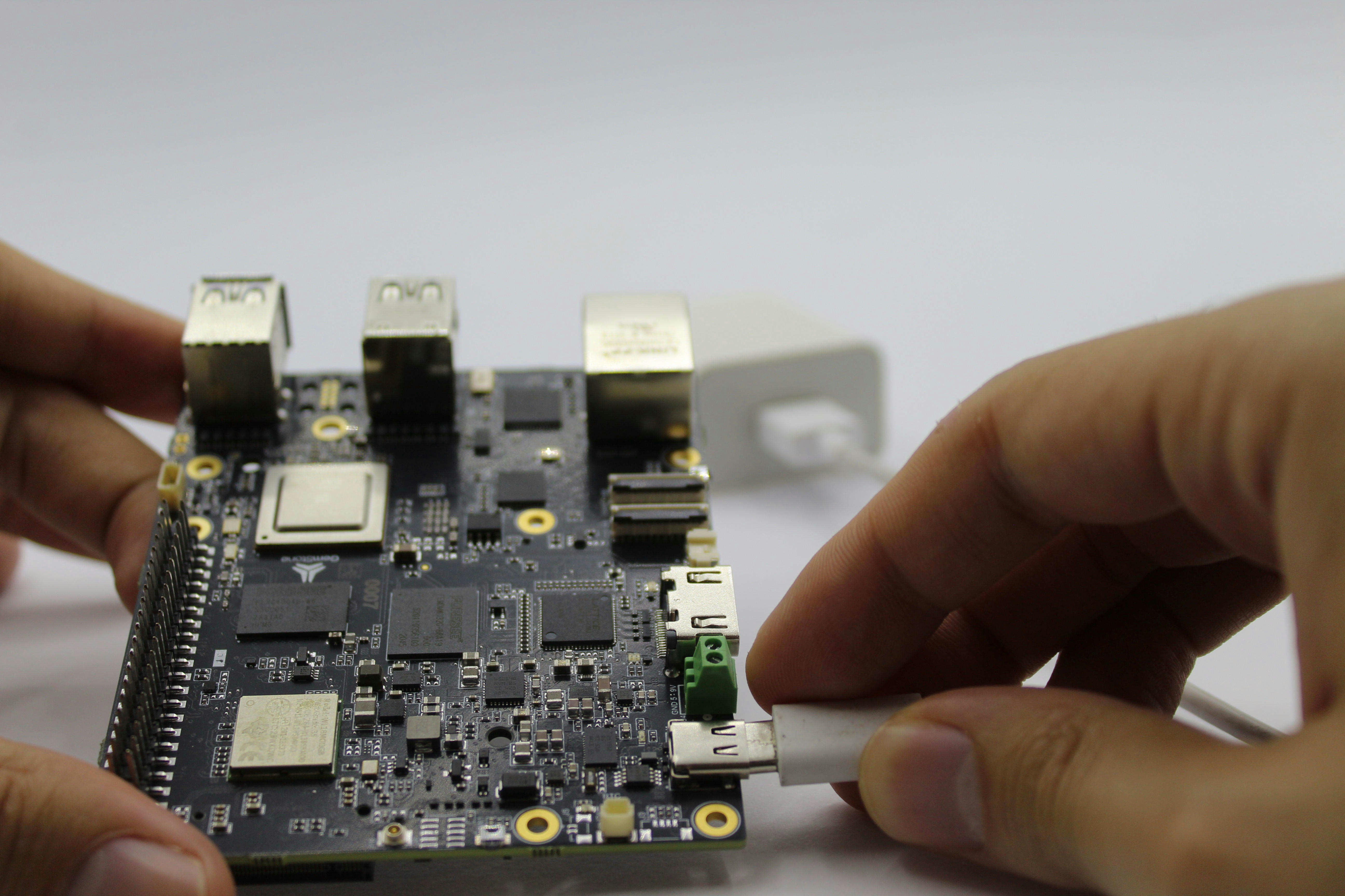
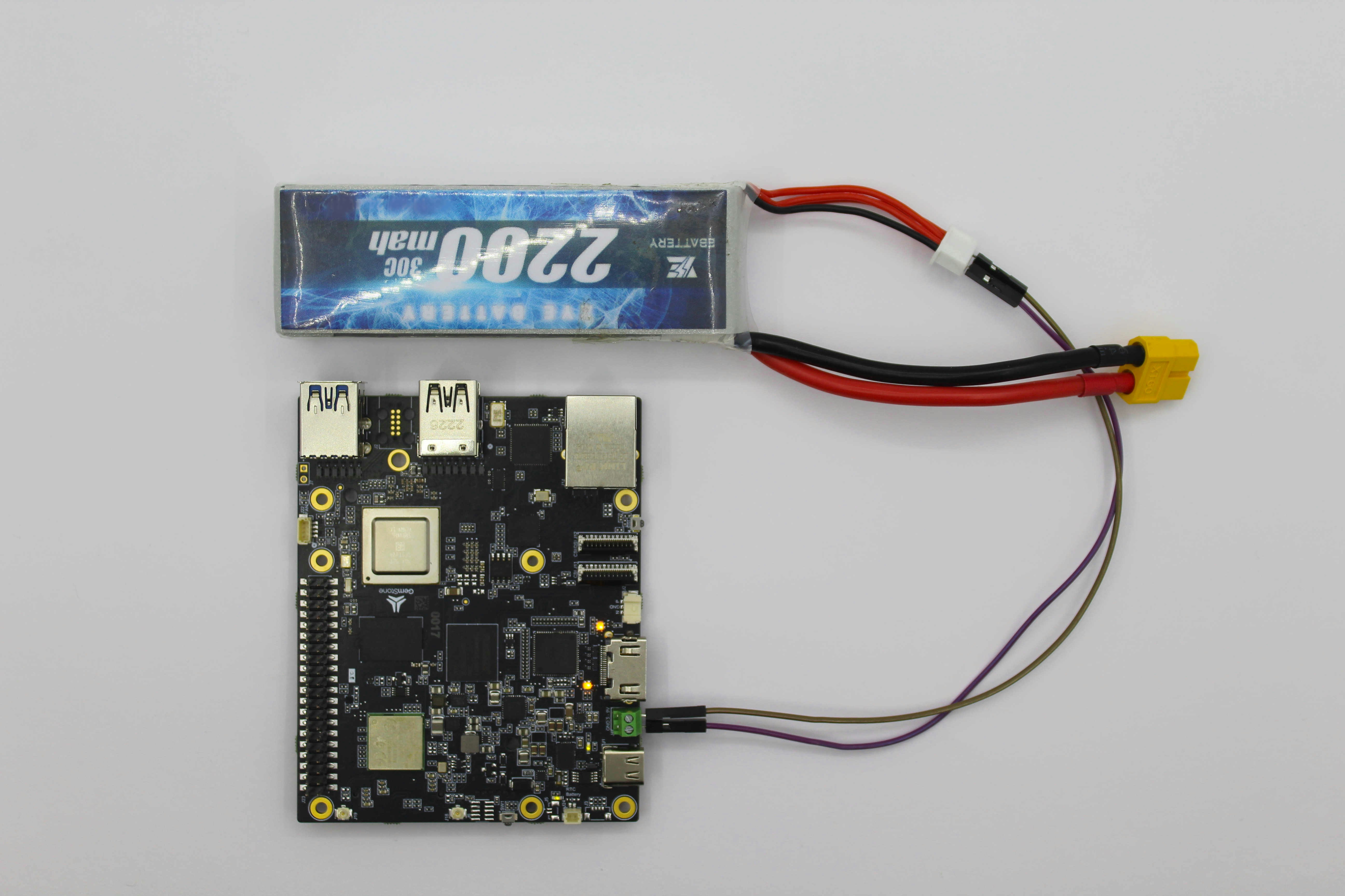
When USB is not connected, the development board is protected against reverse polarity connection to the 12V battery. However, this protection does not provide complete assurance, so the user must connect it carefully.
If the 12V battery is connected backwards while the USB is plugged in, the development board may be seriously damaged and there may even be a risk of fire. Therefore, the polarity must be checked before connecting the battery while the power connection is via USB.
1. Pinout
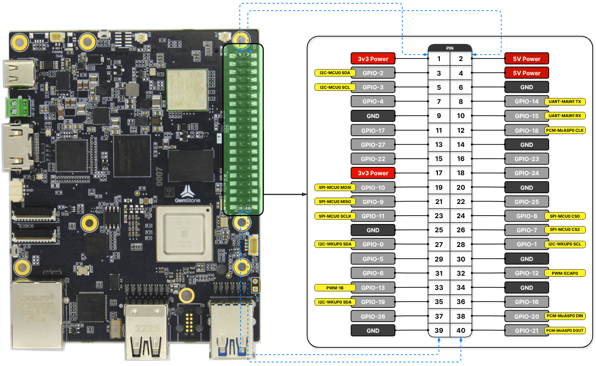
GPIO-7 is configured as SPI-MCU0 CS2 by default but can be converted to
the UART-WKUP0 RX function by activating a file called Device Tree Overlay.
Similarly, in the Gemstone VTOL project, since Bluetooth was not needed,
the relevant pins were disabled and converted to UART-MAIN6.
| 3v3 Power | 3v3 Power | 5v Power | 5v Power |
|---|---|---|---|
| I2C-MCU0 SDA | GPIO-2 | 5v Power | 5v Power |
| I2C-MCU0 SCL | GPIO-3 | GND | GND |
| GPIO-4 | GPIO-14 | UART-MAIN1 TX | |
| GND | GND | GPIO-15 | UART-MAIN1 RX |
| GPIO-17 | GPIO-18 | PCM-McASP0 CLK | |
| GPIO-27 | GND | GND | |
| GPIO-22 | GPIO-23 | ||
| 3v3 Power | 3v3 Power | GPIO-24 | |
| SPI-MCU0 MOSI | GPIO-10 | GND | GND |
| SPI-MCU0 MISO | GPIO-9 | GPIO-25 | |
| SPI-MCU0 SCLK | GPIO-11 | GPIO-8 | SPI-MCU0 CS0 |
| GND | GND | GPIO-7 | SPI-MCU0 CS2 |
| I2C-WKUP0 SDA (reserved) | GPIO-0 | GPIO-1 | I2C-WKUP0 SCL (reserved) |
| GPIO-5 | GND | GND | |
| GPIO-6 | GPIO-12 | PWM-ECAP0 | |
| PWM-1B | GPIO-13 | GND | GND |
| PCM-McASP0 FS | GPIO-19 | GPIO-16 | |
| GPIO-26 | GPIO-20 | PCM-McASP0 DIN | |
| GND | GND | GPIO-21 | PCM-McASP0 DOUT |
1.1. UART-MAIN1
This UART interface can be accessed via the/dev/ttyS3 device on the Gemstone board.
To test the UART line from the command line, you can use the picocom program.picocom is a serial terminal application that sends characters typed on the keyboard in real time to the
specified serial port while also displaying data received from the other end. After connecting the TX and RX pins
with a jumper cable, you can run the following command. If the connections are correct, you should see the characters
you type on the screen.
1.2. I2C-MCU0
This I2C interface can be accessed via the/dev/i2c-1 device on the Gemstone board.
To view the peripheral devices connected to the bus, you can use the i2cdetect command.An example output is provided below. In the command output, peripheral devices marked with
UU (e.g., 0x30) are
connected to the I2C bus but are in use by the Linux kernel, while those with a numeric address (e.g., 0x6b) are
connected and idle.
1.3. I2C-WKUP0
1.4. SPI-MCU0
This SPI interface can be accessed via the/dev/spidev0.0 and /dev/spidev0.2 devices on the Gemstone board./dev/spidev0.0 corresponds to SPI-MCU0 CS0, and /dev/spidev0.2 corresponds to SPI-MCU0 CS2.
To test the SPI line from the command line, you can use the spi-pipe program.spi-pipe sends data from stdin to the SPI line specified by the --device setting and outputs the data received
from the line to stdout. After connecting the MOSI and MISO pins with a jumper cable, you can run the following
command. If the connections are correct, you should see the text “Hello World” on the screen.
1.5. PWM-1B
This PWM interface can be accessed via the/sys/class/pwm/pwmchip5/pwm1 device on the Gemstone board.
For this device to be created, the export command must first be executed.Then, the
period and duty_cycle values in nanoseconds can be set to the desired values as shown in the example
below. After enabling the device with the enable command, the PWM output can be obtained.
1.6. PWM-ECAP0
This PWM interface can be accessed via the/sys/class/pwm/pwmchip0/pwm0 device on the Gemstone board.
1.7. PCM-McASP0
Pulse-code Modulation (PCM), or Multichannel Audio Serial Port (McASP) as it is called in Texas Instruments SoCs, can be used in real-time audio processing applications requiring low-latency and high-quality digital audio streaming. TheFS pin provides a frame-sync signal to an external audio device like a DAC, while the CLK
pin similarly provides a clock signal. The DIN pin allows data input from a digital audio device like an
I2S microphone, and the DOUT pin allows data output to a digital audio device like a DAC.
2. Device Tree
The configurations (UART, PWM, I2C, GPIO, …) that the 40-pin I/O ports on the board can be used for are defined in files called Device Tree Overlay. To activate the desired configuration(s), the relevant overlay files must be found and provided to the bootloader as a list. For Texas Instruments ARM64-based SoCs, the source code for all overlay files is located in the t3gemstone/linux project under thearch/arm64/boot/dts/ti directory.
Those for the T3-GEM-O1 board are named in the format k3-am67a-t3-gem-o1-<overlay_name>.dtso. Each overlay
file includes information at the beginning about its purpose.
2.1. Example: Routing UART6 signals to the 40-pin HAT
By default, the T3-GEM-O1’s 40-pin HAT has only one serial port. For projects requiring multiple serial ports, other pins on the 40-pin HAT must be converted to serial ports.2.1.1. Examining the Pinout
When examining the T3-GEM-O1’s pinout, it can be seen that pins 7 and 11 on the HAT can be used as UART6_RX and UART6_TX.2.1.2. Finding the Relevant Overlay File
The next step is to determine which Device Tree Overlay file provides the desired configuration. All Device Tree Overlay files are located in the/boot/overlays folder on the development board. They can be listed by running the ls /boot/overlays command.
2.1.3. Updating the uEnv.txt File
In this example, thek3-am67a-t3-gem-o1-uart-ttys6.dtbo overlay file will be used. For the bootloader to load
this file before the operating system starts, it must be added to the overlays section in the /boot/uEnv.txt
file as shown below. Overlay file names are added with a space between them.
overlays=k3-am67a-t3-gem-o1-spidev0-2cs.dtbo k3-am67a-t3-gem-o1-i2c1-400000.dtbo k3-am67a-t3-gem-o1-uart-ttys6.dtbo
2.1.4. Verification
After saving the changes, the board should be rebooted using thereboot command.Then, the
ls /proc/device-tree/chosen/overlays command can be used to check whether the overlay has been added.
/dev/ttyS6 device will be created.